Day 1
Day 2
Day 3
Day 4
Day 5
Day 6
Day 7
Day 8
Day 9
Day 10
Day 11
Day 12
Well, it took nearly a full day of work, but the WX-500 processor is fully installed in the rear of the plane. Let's break it down step by step:
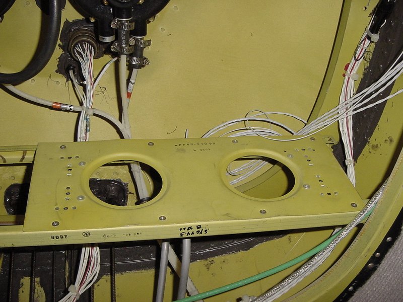
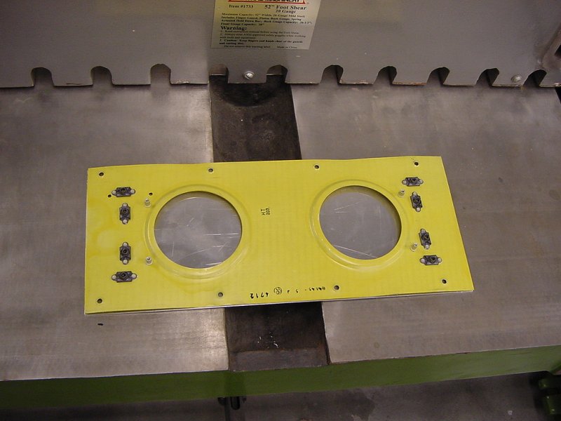
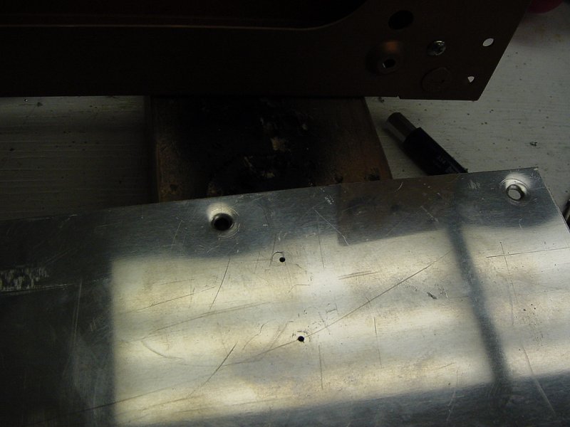
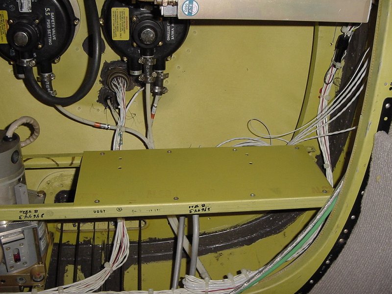
On the lower shelf of the rear equipment bay in front of the rear pressure bulkhead was a space off to the right ideally suited for mounting additional equipment. However, it was pre-cut for other pieces of hardware and the standard Piper shelf was unsuitable for mounting the WX-500 tray on. Here you can see why:
The two large holes cut in the middle of the shelf meant that only three of the four mounting points could be accomodated. After considering the possibility of making another piece of metal that screwed on to the existing shelf that would allow the WX-500 to be mounted properly, I decided it would be better to just make a whole new shelf. This meant cutting a new piece of aluminum to the old shelf's dimensions and then drilling all the holes in the appropriate spots.
After finding an piece of scrap laying around that was large enough to be cut down to the right size and thick enough to support mounting a piece of equipment to, I needed to scribe out the dimensions of the cuts.
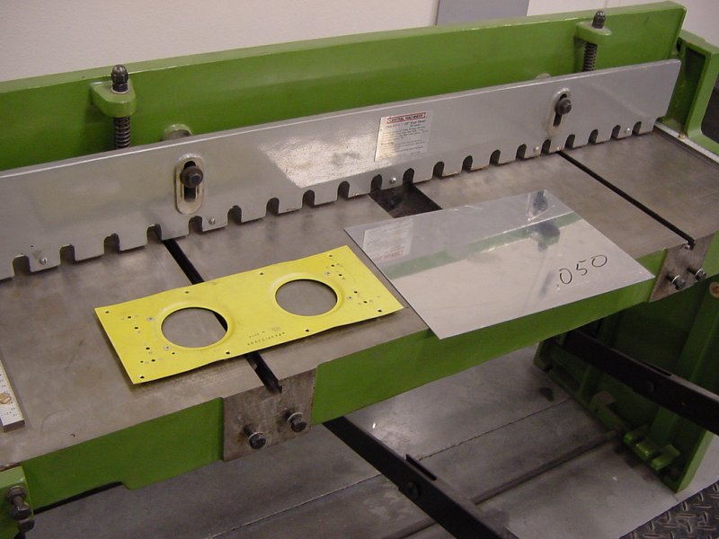
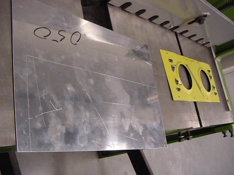
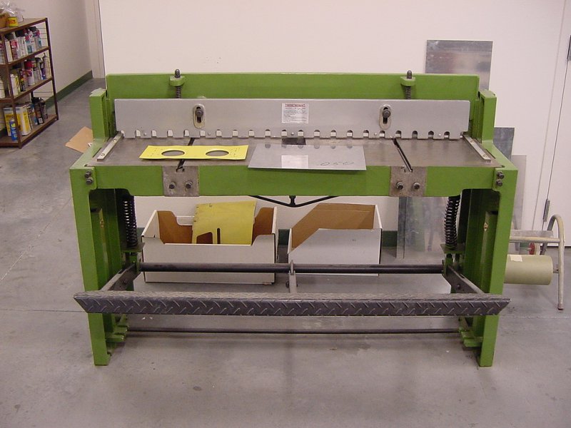
Once the lines are marked, I get to use a wonderful device called a "shear" (or guillotine) to make the cuts. Compared to trying to cut metal with tin snips, this foot-operated device is amazingly easy to use and makes perfectly straight cuts. It's essentially a paper cutter for metal.
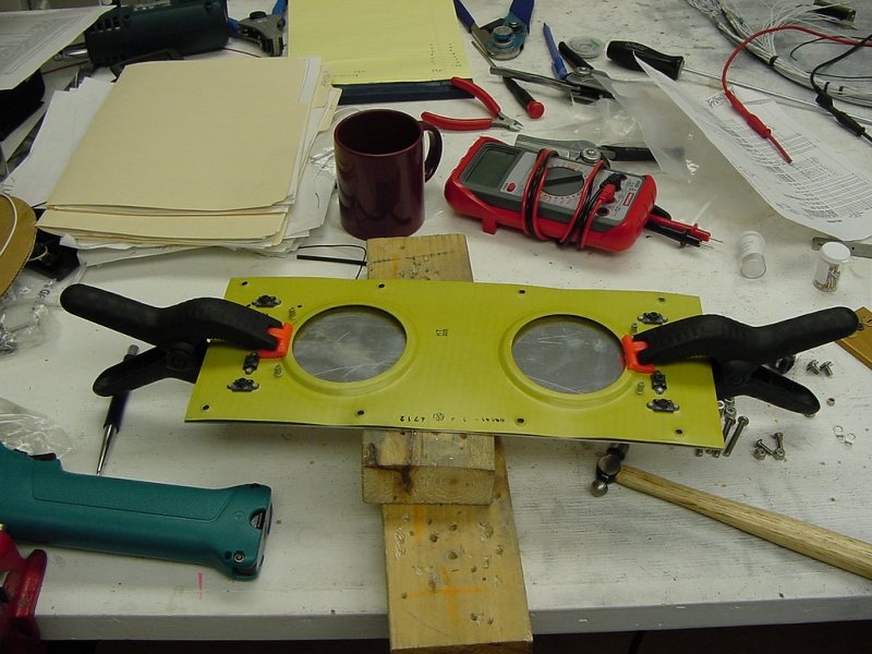
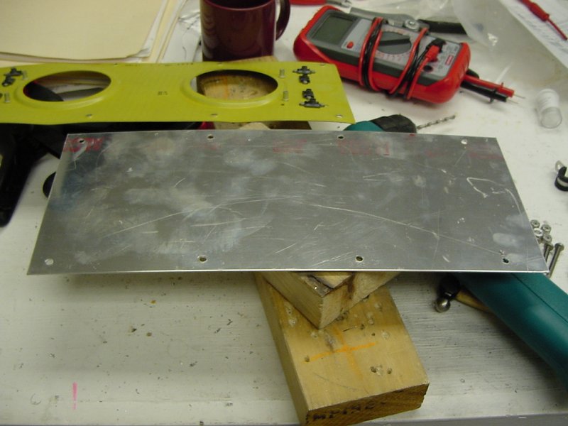
So once the new shelf is cut, it needs to be drilled with the holes used to mount it to the rails in the back of the plane. These are 8 countersunk holes, 4 on each side. The easiest way to do this is to clamp the two pieces together and use the holes on the orignal piece as a guide.
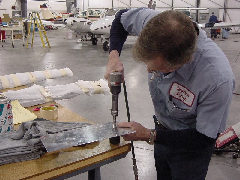
Since the holes need to be countersunk, and you can't cut deep countersunk holes into sheet metal, the countersinking needs to be done by pressing instead of drilling. To do this, I asked the resident sheetmetal expert if he could help me out. He used a die attached to a pneumatic hammer that effectively countersinks the holes in aluminum.
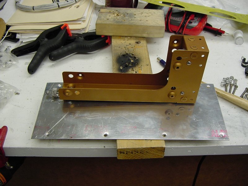
The next step was to drill the holes for mounting the WX-500 tray. As you can see in the detail picture above, this is done by first drilling pilot holes. The pilot holes are drilled where a center punch is used to mark where the holes should go. To figure out where the holes should go, I simply placed the tray on top of the metal and punched in the center of the holes. After two holes were drilled, I placed a couple screws through them to help make sure everything lined up and then punched and drilled the other two holes.
The final step to fabricating the new shelf was to give it a coat of zinc chromate paint. Zinc chromate is the yellowish paint seen on the insides of planes before they're covered with metal or upholstery. This is used as a corrosion inhibitor and even though the back of a plane is generally pretty dry, we gave it a coat so that it matched the existing metalwork.
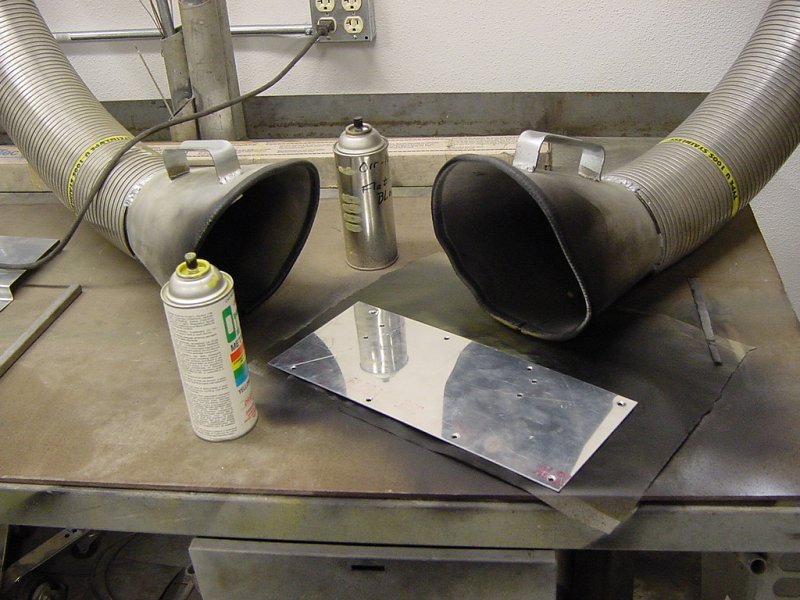
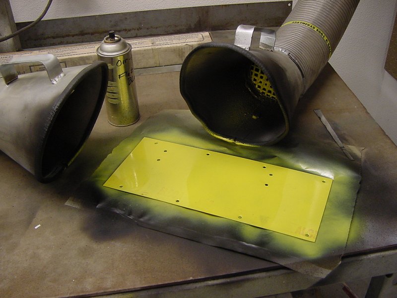
The funnel-like things sitting behind the freshly painted shelf are part of a ventalation system that sucks the paint overspray and fumes outside. This is much better than having to wear a face mask and smells better, too.
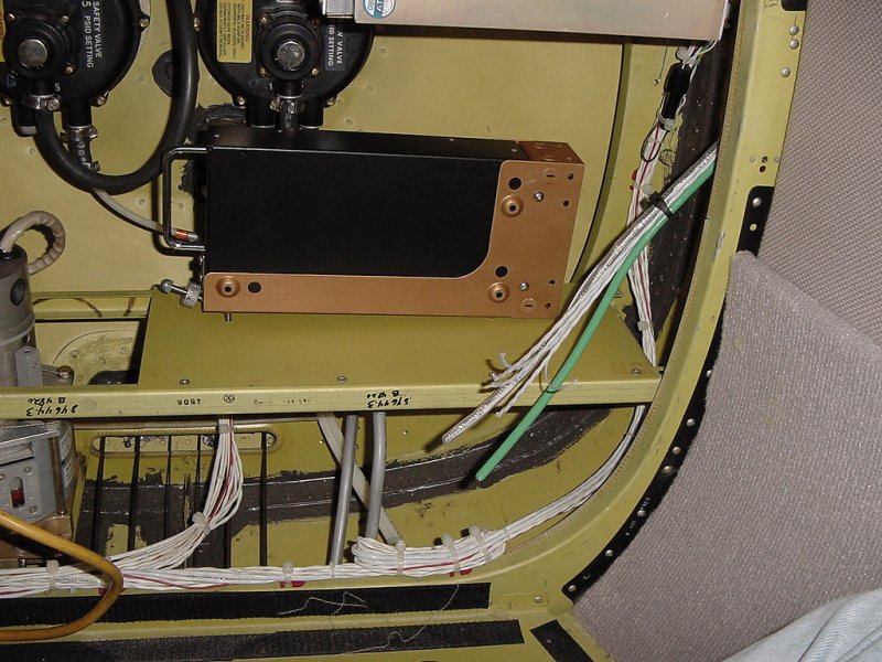
After the paint dried (which was fun to watch) and the new shelf was mounted in the plane, it looked pretty natural sitting next to all the facotry Piper stuff - which is just the intended effect.
Now that the shelf was ready for mounting the tray, it was time to terminate all the wires heading to the back of the plane and put them in the connectors.
Since the cables are already routed at this point, there isn't any slack going forward. To ensure that they are cut at the proper length, I tie-wrapped them into place heading to the back of the plane up to where they will be stripped and terminated. This allowed me to place the tray in place and get an accurate measurement of exactly how much wire would be necessary to reach the back of all the connectors. When using hundreds of tiewraps, it's effective to have a tiewrap gun instead of using your hands and diagonal clippers (flush cut, please). You can see what it looks like here:
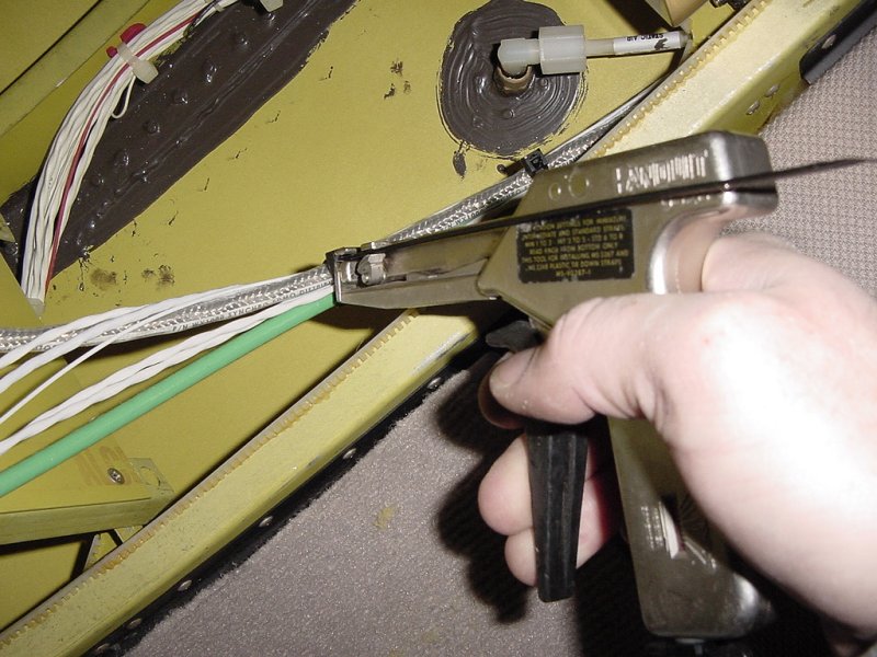
The gun pulls the tiewrap tight and at a pre-set tension, a blade comes up and clips the excess off right up against the lock so that people fishing around won't get thier hands cut by sharp plastic.
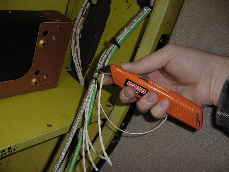
With the tray in place, and the cables all tidied up, I can cut off the excess lengths without worrying about being an inch short. Sometimes you can just cut longer than necessary, but due to the stiffness of the cables, excess wouldn't work.
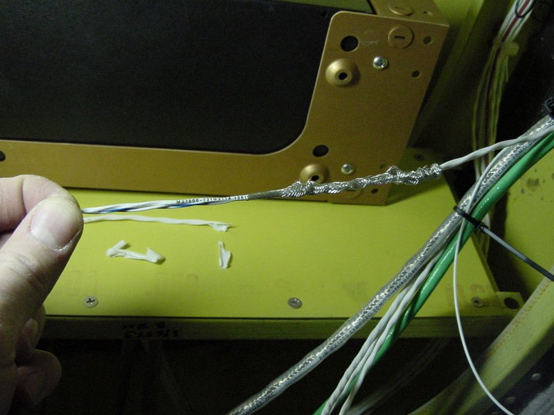
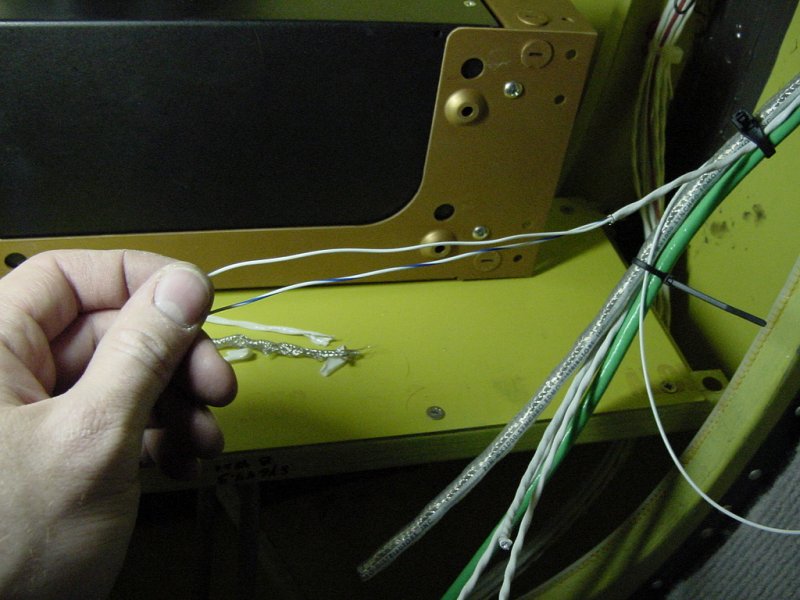
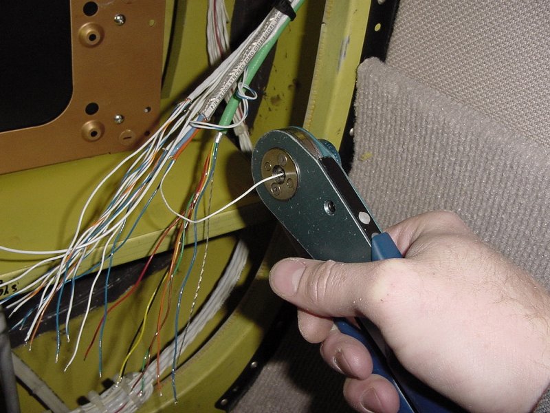
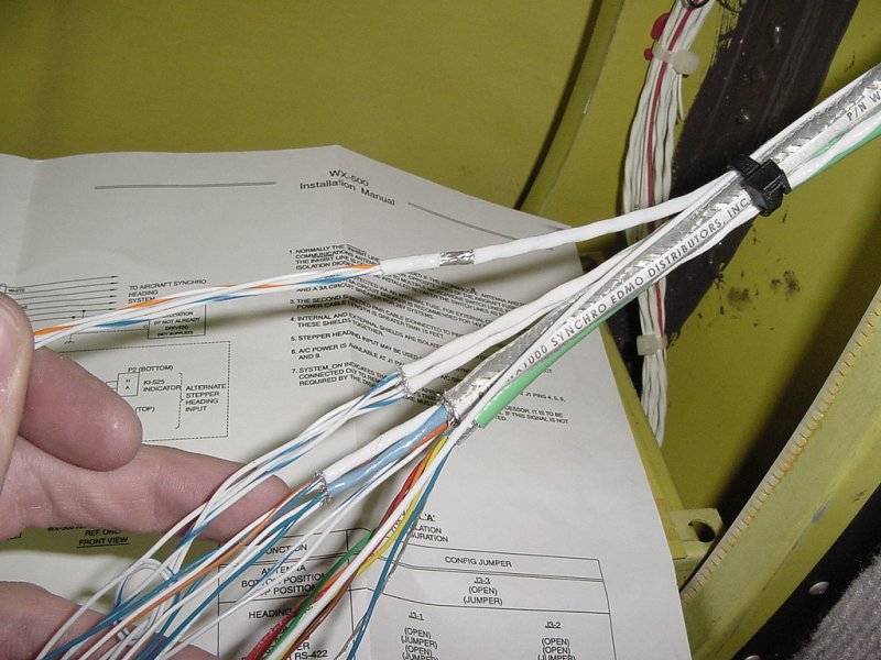
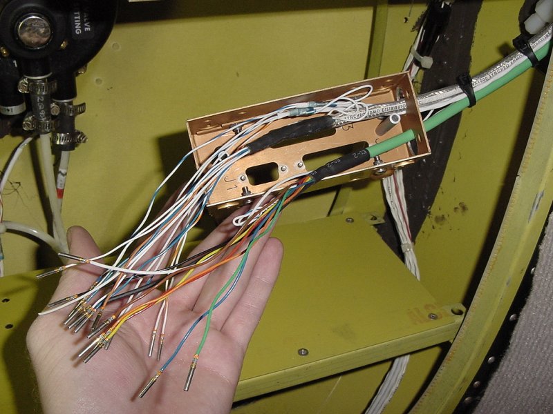
To do this, a razorblade is used to cut the sheath (wire strippers won't work due to the unevenness of the wire and the snugness of the sheath against the shielding). Once this is done, the shielding can be cut back to the sheath. Finally, the wires can be stripped in preparation for crimping on the connectors.
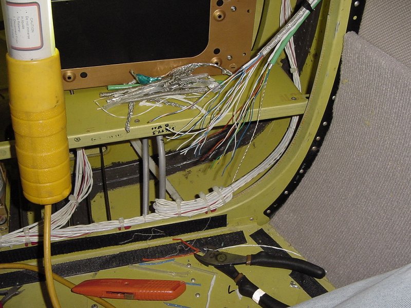
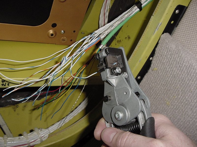
After stripping all the cables, the interior wires need to be stripped and then they need to have the connectors crimped on. These are all going into D-type plugs, so to crimp on the connectors, a special crimper is used which pushes on the wire from four sides at just the right pressure based on the gauge of wire used. These wires are both 22 and 24 gauge, so two settings are used depending on what's getting crimped.
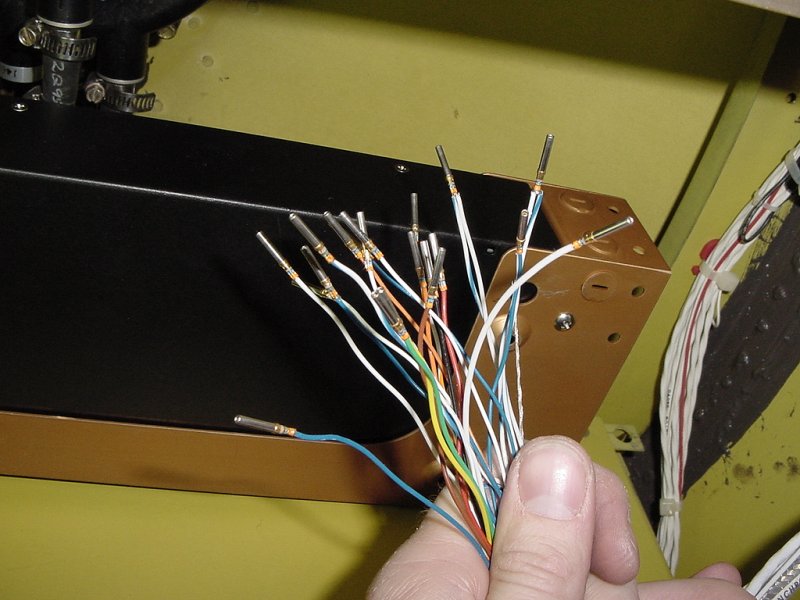
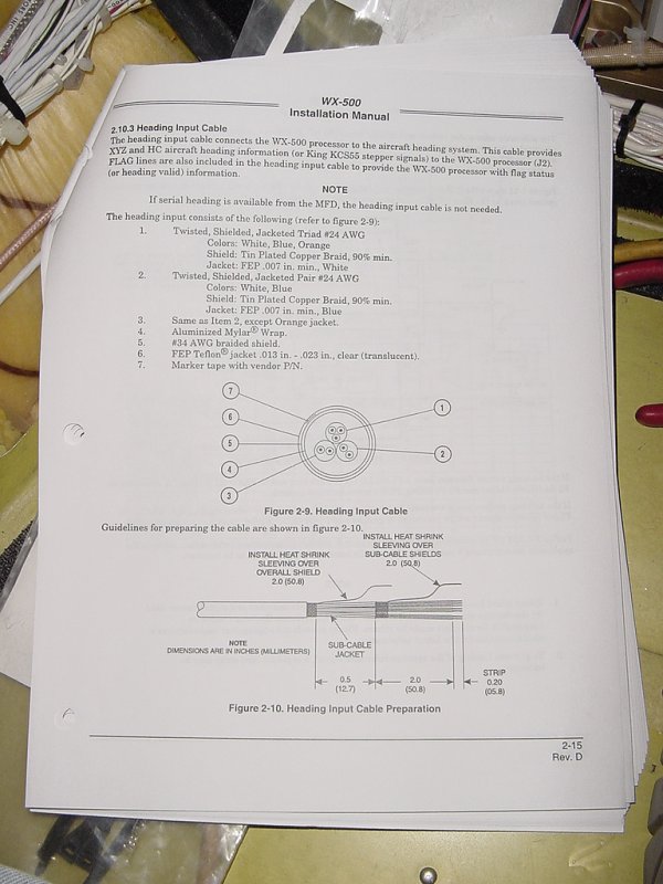
Based on the wiring diagram (shown below), each of the shielded wires except the antenna needs to have its shield grounded at the processor to prevent electrical noise from seeping into the wires. To do this, a small piece of the sheath is pulled down over the end of the shielding and a wire is soldered to it useing heat-shrink tubing with solder rings inside. Each shield grounding wire is daisy chained along until the final wire, which is run to ground. Finally, the shields not needing grounding are covered with heat shrink tubing.
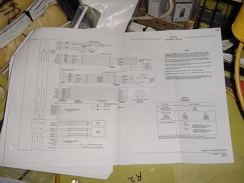
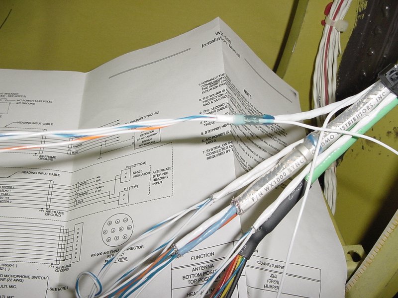
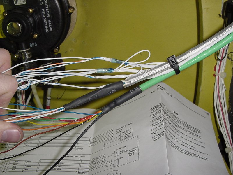
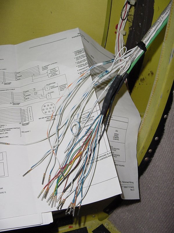
Now that the wires are all ready to be inserted into the D-type connectors, I fed them through the holes in the tray and inserted them into the correct places according to the wiring diagram.
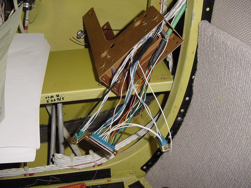
One of the last steps is attaching the connectors to the back of the tray, which is done with standoffs instead of nuts - presumably because it's easier for the poor installer who just spent 4 hours stripping and crimping wires.
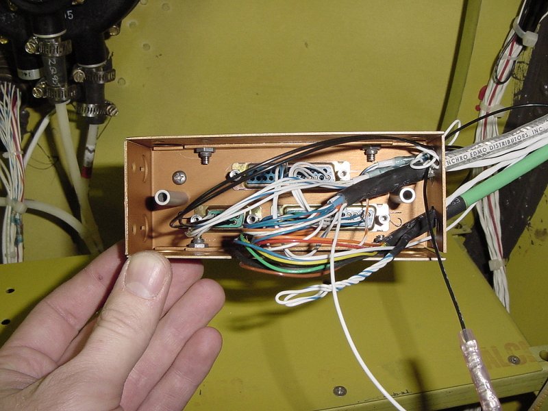
Finally, the wires are clamped in place to keep them from sliding about and the back cover it put on the tray. Once this is done, the tray is screwed down to the shelf. All done, and it looks pretty good - as it should considering this process took nearly a full 8 hour day to accomplish.
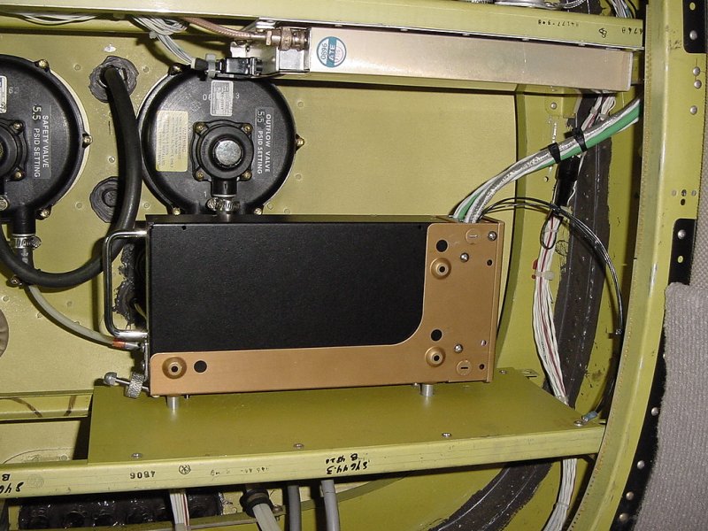
The back of the plane is in pretty good shape now - we have the WX-500 mounted and the antennas in place. The only thing left to do is hooking up the 530 in the panel and running the power wires. After that comes the power on test and the interior reinstallation. See you tomorrow!
Day 1
Day 2
Day 3
Day 4
Day 5
Day 6
Day 7
Day 8
Day 9
Day 10
Day 11
Day 12