Day 1
Day 2
Day 3
Day 4
Day 5
Day 6
Day 7
Day 8
Day 9
Day 10
Day 11
Day 12
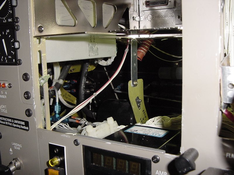
Today we'll be reinstalling all the avionics. This starts with mounting the tray for the 530 and then progresses to the remaining KX-165. Since the 530 pushed down the 165 just a tad, two of its mounting screws don't have a place to go. When the radio is only supported in the front by two screws, the rear has to be strapped down as well.
As you can see in the picture below, the mounting rails are occasionally reenforced tying the front and back strips together. I could just drill holes where the KX-165 needs them, but this would weaken the mounting rails too much considering how sparse these reenforcements are already.
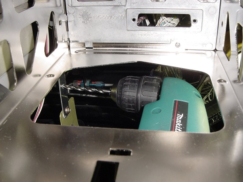
The rear support needs to have a hole drilled at the appropriate spot to match up with the rear mounting hole of the KX-165 tray. In the picture above, you can see where I marked it.
Once marked, a small hole is drilled as a pilot hole. This keeps the larger drill bit used to drill the actual hole from dancing around on the metal and going off course.
Next, the larger hole is drilled and a speed-nut is put in place to give the screw something to ... screw.
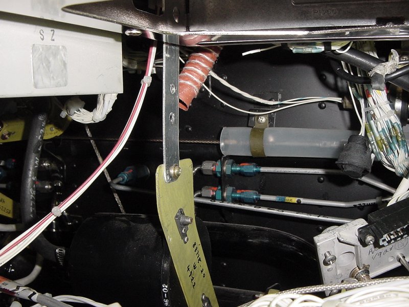
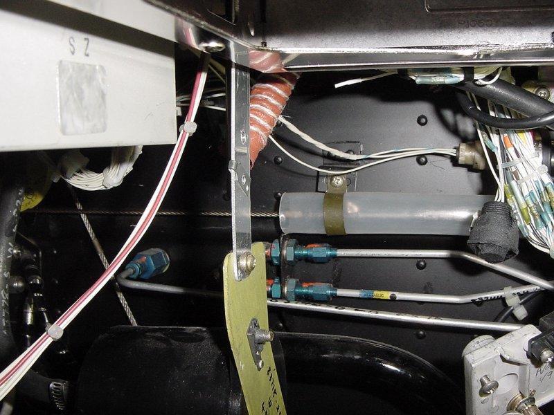
Now that the rear support is ready, the back of the tray is screwed to the support, and then the front screwed down in place.
The last thing necessary for mounting the 165 is reconnecting the cooling air supply. This is a rather inconveniently placed fitting on the back of the radio. To get to it, I have to go under the panel and clamp it on. (You can also see the back of the rear mounting screw and the rear support in these pictures.)
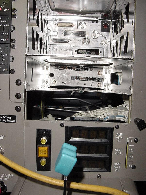
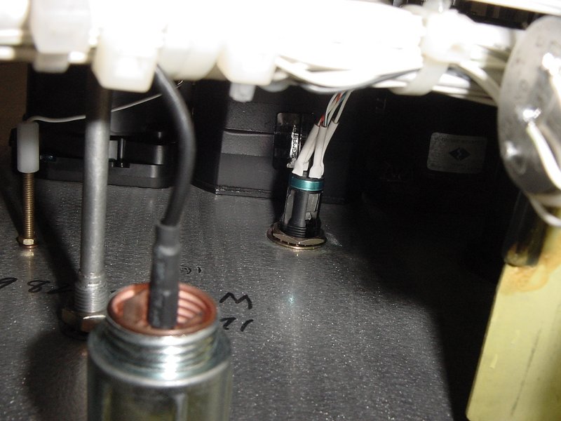
Before mounting the avionics in the right stack, I need to remove the old KLN-90B data loader jack. This is a connection to hook a computer up to the panel to load the GPS with its database. On the 530, it takes flash cards plugged into the front of it, so this isn't necessary and needs to come out.
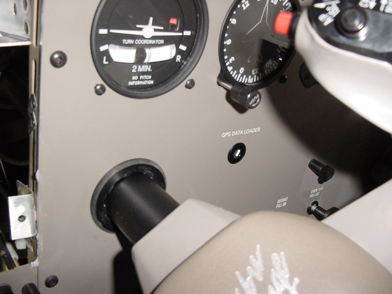
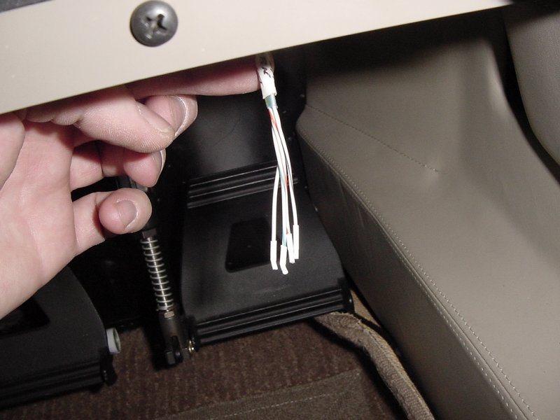
The first step in doing this is removing the nut holding the jack to the panel. This is a very difficult to reach nut due to the number of things mounted around it. Because of this, there isn't much room to swing a wrench. Once I got it loose though (maybe 1/4 turn), I did the rest with my fingers. The jack is then clipped off and the loose wires shrink wrapped to prevent shorts. In this case, it isn't too important since the other end of it is also clipped and shrink wrapped.
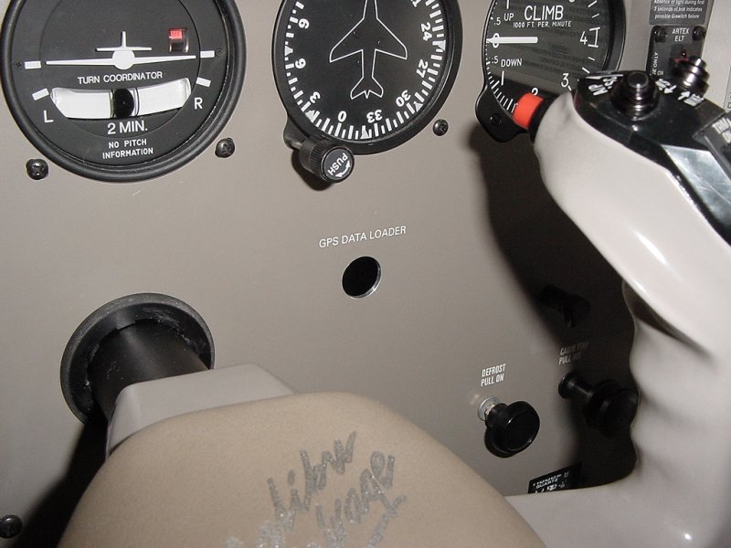
The hole will be filled with a plug painted to match the panel and the silk-screened lettering will be removed and painted over as well. This will happen at the very end of the job.
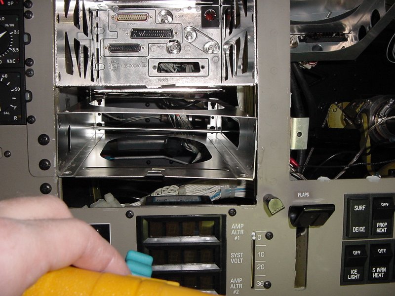
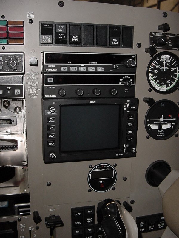
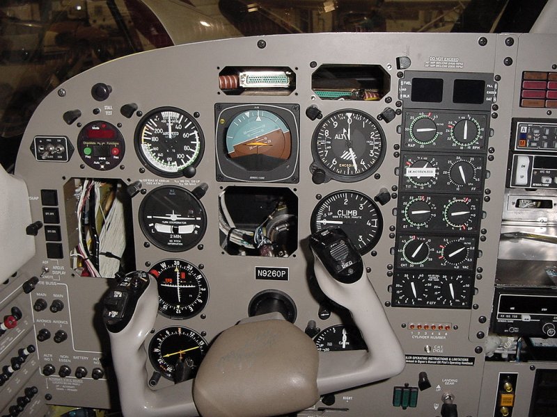
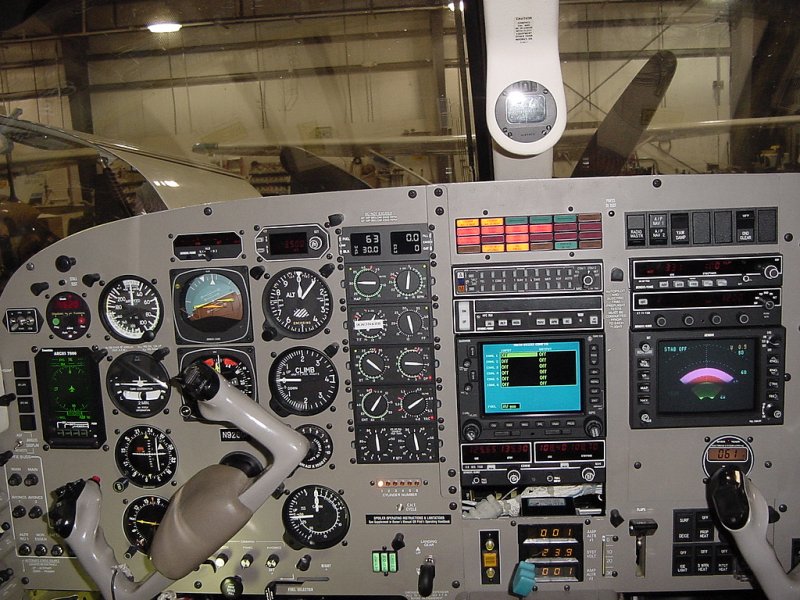
With that done, it's time to reinstall the right stack's avionics. The trays for the ADF and transponder are remounted and the radios installed. Then it's time for the radar display to go in. To complete this stack, the TIT (Turbine Inlet Temperature) gauge is mounted at the bottom.
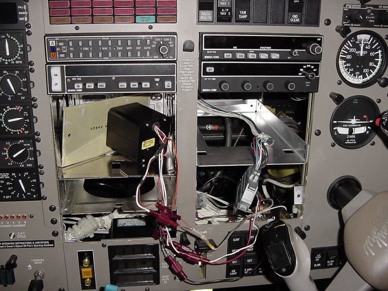
Oops. As sometimes happens in these installs with so many wires going so many places, something gets forgotten. When I removed the old KX-165, I meant to move its swap its power with the second 165. This is because this plane is equipped with a "Ground Clearance" switch that allows the pilot to power one radio, the audio panel, and the intercom without switching the whole plane on. Powering the comm side of the 530 won't do any good since the GPS side is what powers the display and controls (plus, waiting for a 530 to initialize is sometimes annoying).
Well, I pulled the power off the old 530, but then didn't swap it with the power for the remaining KX-165. As a result, these two radios and their trays have to come back out so I can swap these lines. Fortunately, it's fairly easy and accomplished with a couple well placed splices, but it's never fun to do your work twice.
Also, since I'm changing the power leads to the radios, I also have to swap the power leads at the breakers. Because of how the ground clearance circuit is wired, I can't just swap the breaker wires and be done with it. It would've been more convenient if there were a "Ground Clearance" bus, but that power actually goes through fuses in the battery compartment, so subsequently, this is the "right" way to do it.
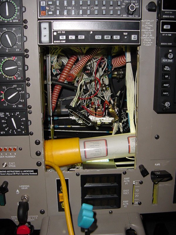
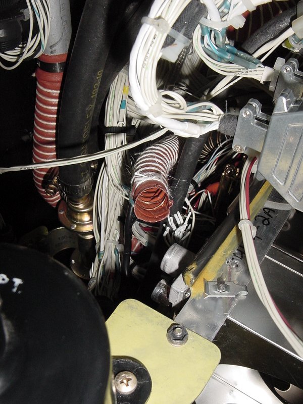
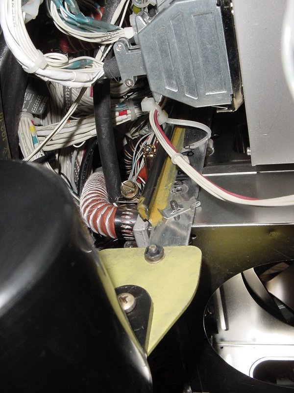
While redoing most of the steps above for installing the 530 and 165, Duane was struggling with the Argus reinstallation. Due to how it is mounted, a major bundle of wires (seen in the picture below) goes through the same space that it wants to occupy. After an hour or so of wire wrangling, he managed to get it in. After that, the HSI was a relatively straightforward task.
With everything plugged in, it was time to do a test of interconnections and power lines. I turned everything on and made sure the Garmin was talking properly to the Argus, DME, HSI, transponder, audio panel, and Stormscope.
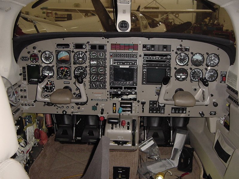
With that done, it was time to make sure everything underneath was tidied up one last time and reinstall the glareshield over the panel.
Well, it's the end of another day. Tomorrow will concentrate on reinstalling all the upholstery pieces and doing a engine-run test to make sure everything works acceptably.
Day 1
Day 2
Day 3
Day 4
Day 5
Day 6
Day 7
Day 8
Day 9
Day 10
Day 11
Day 12