Day 1
Day 2
Day 3
Day 4
Day 5
Day 6
Day 7
Day 8
Day 9
Day 10
Day 11
Day 12
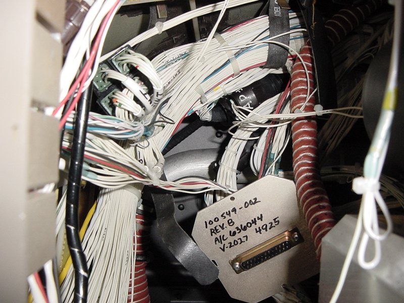
The third day of installation started out with me thinking I might start clipping the wires off the old connectors and plugging them into the new ones. Well, after a few moments of thinking, I realized that in order to do this, I first had to find a relay. In some planes that have more than one primary navigation radio (such as VOR and GPS in this plane), a switch allows either one or the other to be displayed on the primary navigation indicator (the HSI). However, this involves switching more than a dozen wires, so instead of a huge switch, a ganged relay is used.
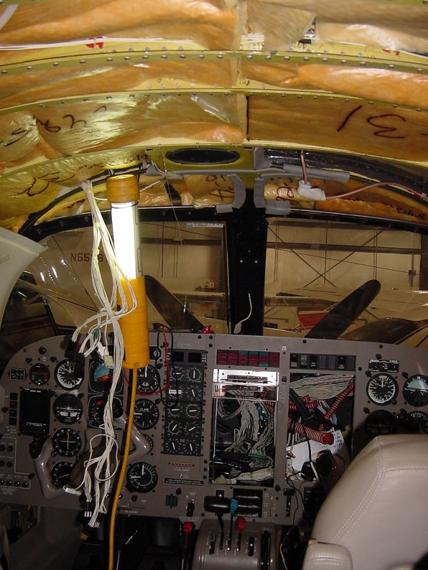
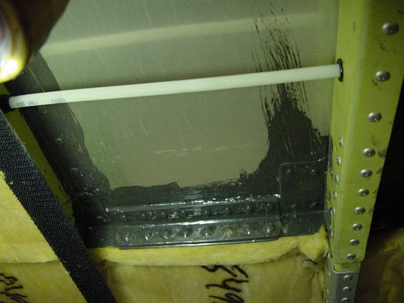
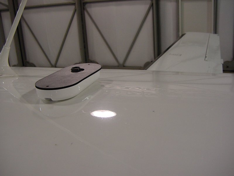
Since in this installation we're pulling out these two radios and replacing them with an integrated unit, this relay is not necessary and must be found and pulled out. While adventuring around the interior bits trying to track down this smallish box with 50 or 60 wires hanging out of it, I removed the overhead panel, thus exposing the back of the GPS antenna we're replacing with a new unit.
You can see the RG-400 coax going to the GPS antenna on the upper right side. However, by pulling out the overhead panel, another very important switch became disabled - the battery master. Without this switch, no magic can happen and no further power-on testing can be done. Since this will be crucial to finding the aforementioned relay, the panel will have to go back in. But since the GPS antenna is now exposed, let's take it out and put in the new one.
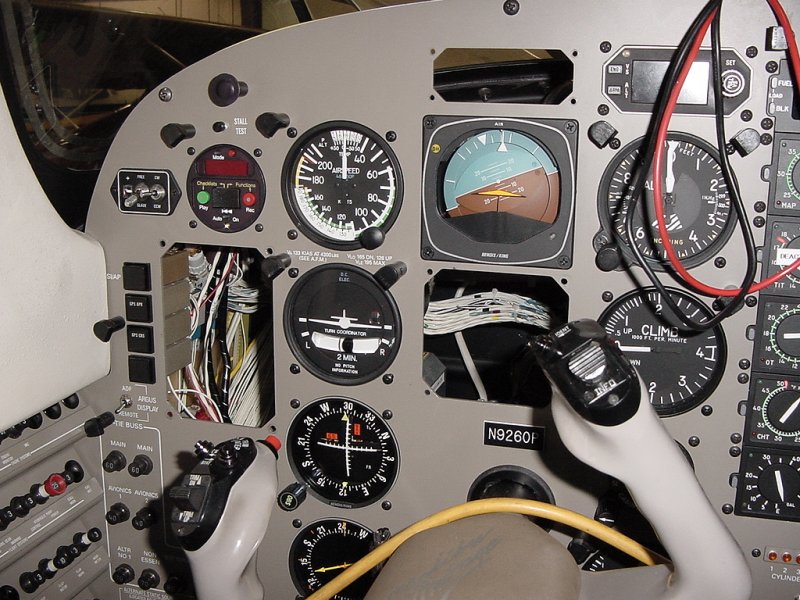
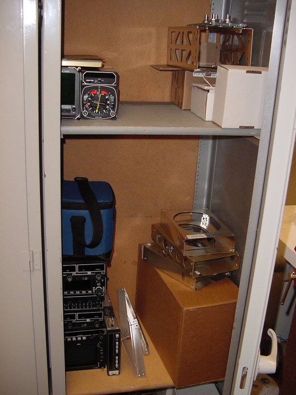
But before getting in to that, here are some pictures taken during my poking around in the panel. The Argus display (soon to be somewhat redundant), the HSI, and the DME remote are all pulled out in these pictures. Remember the bit where I said that things in our way get removed temporarily... well that's why these came out. Not only were they cluttering up the guts of the panel and making it hard to get my hands around and between things, but by removing them I get valuable holes to stick my hands through to trace wires.
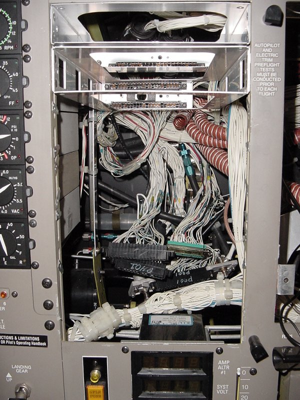
As you can see, the equipment is starting to pile up in the cabinet:
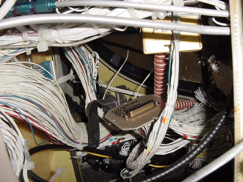
Right then, now that you see what my life is consumed by (wires), let's install that GPS antenna. Since we're replacing an existing antenna, sometimes the footprints match and no drilling is necessary. Unfortunately, the antenna coming out is bigger than the one going in. This means that a couple new holes will have to be made in the skin.
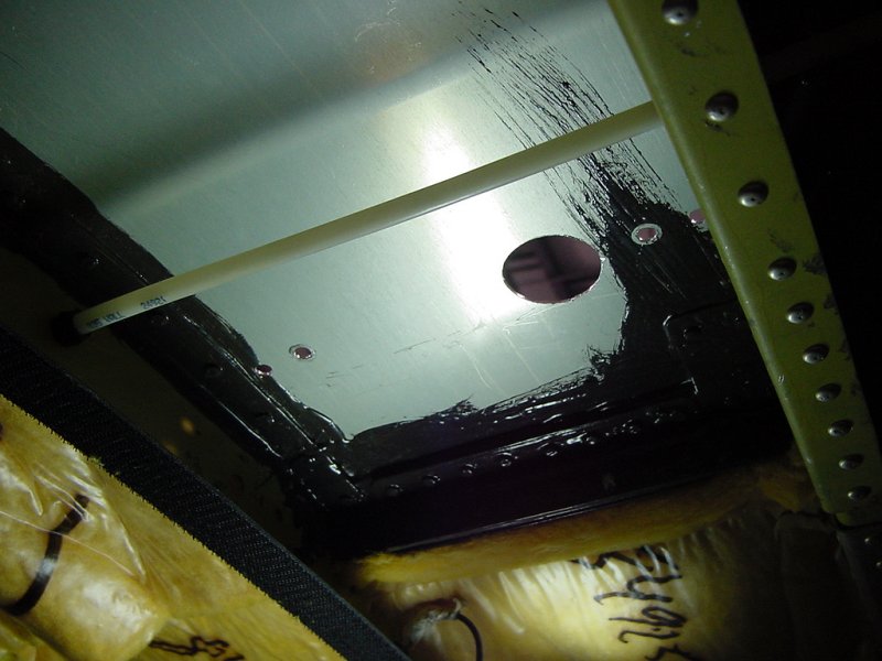
First, we pull off the old antenna, exposing the unpainted aluminum below. You can see the existing back-plate (doubler) on the inside. The gray goop slathered all over it is called PRC, a sort of rubberized epoxy which is used for sealing the holes you poke in pressure vessles.
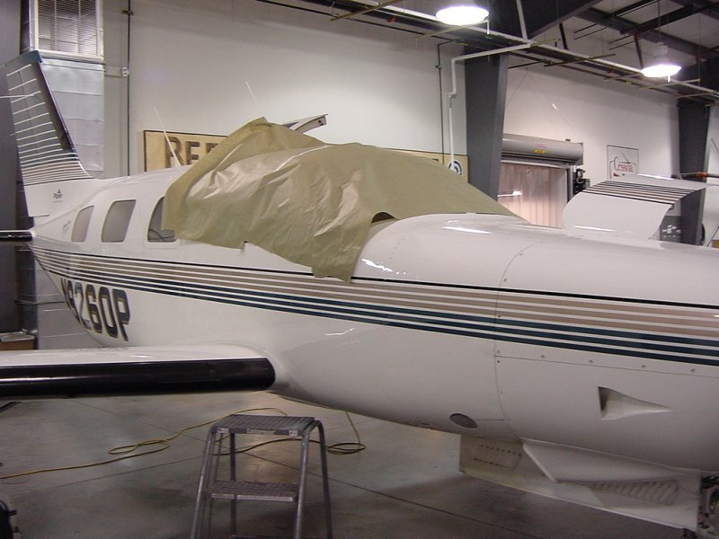
Since the new antenna is smaller than the unpainted area, we need to give it a thin coat of paint to protect it. Since we're an avionics shop - not a paint shop - matching exact colors and glosses and extensive preparation is not necessary. This is more or less just to allow the plane to pass at a glance.
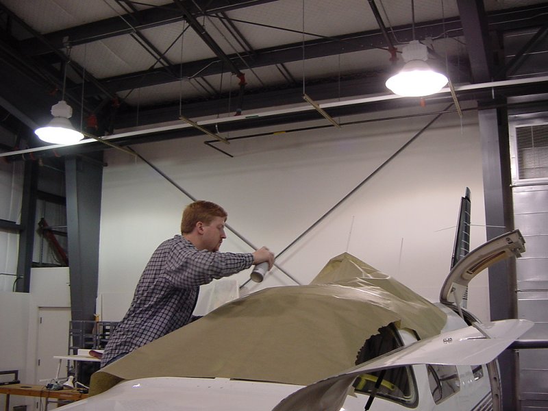
The first step in covering the area is masking off the existing paint and surrounding area so that it doesn't get covered in overspray. Of primary importance here are the windows - since they're made of plexiglass, paint can't be scraped off them with a razor blade. The holes are covered with tape so that the interior isn't filled with paint (leather also doesn't like overspray).
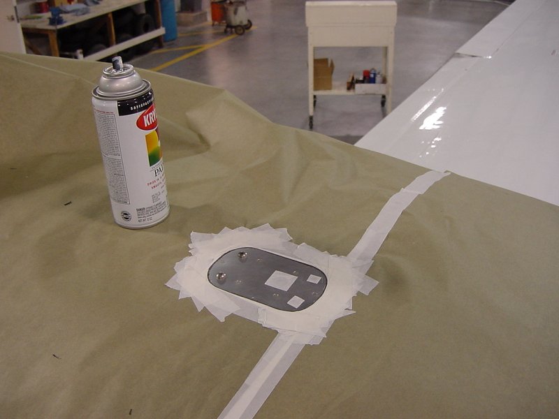
With the area appropriately masked off, the painting can begin. I gave it two coats which covered the area thouroughly in paint, but left it thin enough that it could be replaced with a proper paint job in the future without too much removal effort.
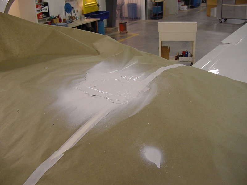
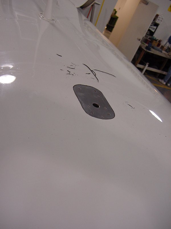
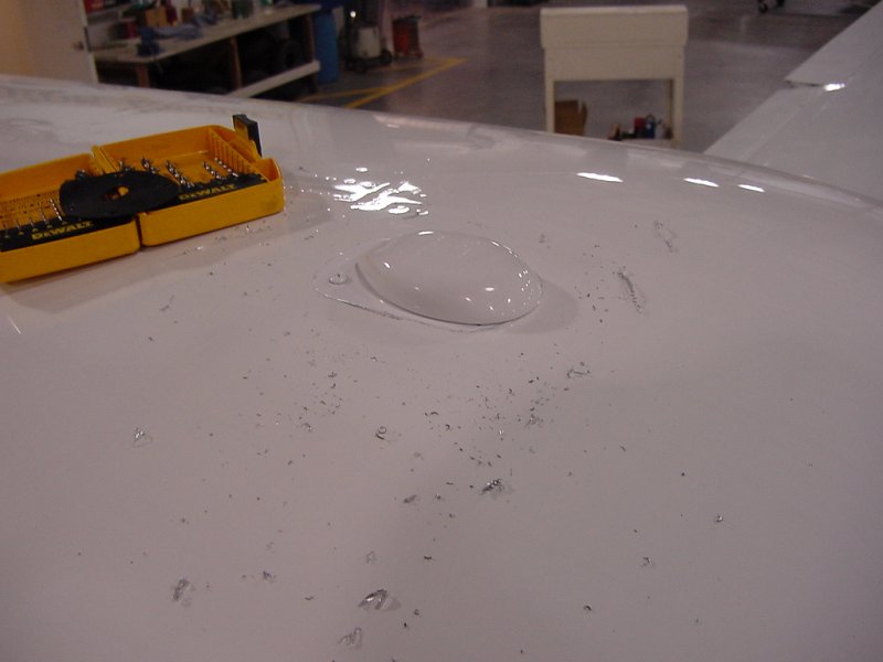
After the paint dried a bit, I pulled off the masking to see how it came out. The paint used was a little whiter than the white of the plane, but generally came out looking good.
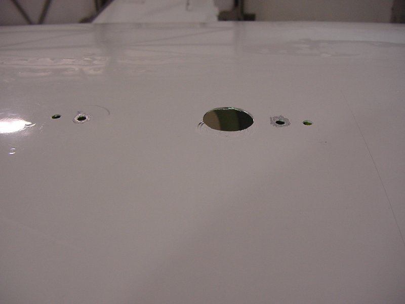
The next job was drilling the new holes. Aluminum comes out in nice stringy bits since it is a very soft metal, so you can see them laying all around the holes.
The PRC used to cover the insides of the antennas is a pre-measured kit that set in 20 minutes. Because of these constraints, it's best (and more cost-effective) to do all your PRC work at once instead of mixing multiple batches.
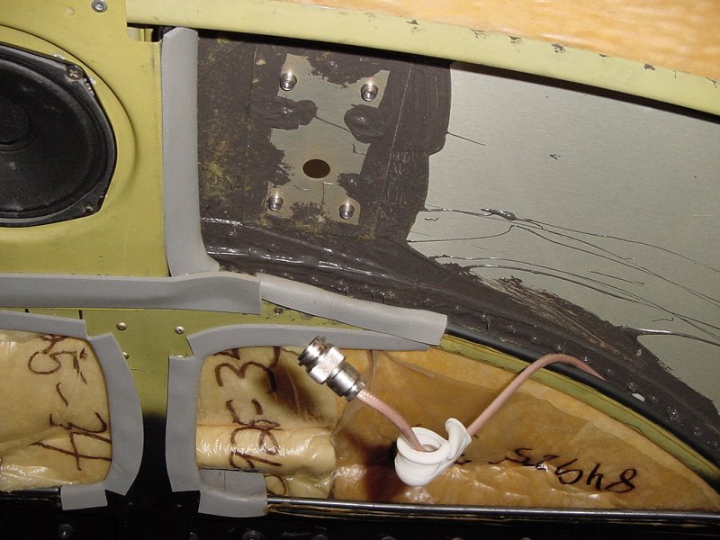
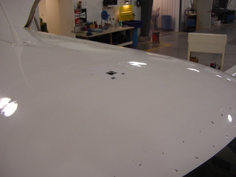
The WX-500 antenna that we did the skin mapping for also needs to be mounted and sealed with PRC, so we drilled the holes for this next. Here's the interior and exterior locations for where the antenna back plate will be installed:
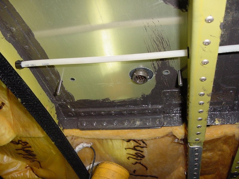
After drilling some more holes in this million dollar aluminum, this is what it looks like. You can see the tight tolerances for mounting this antenna. It's just about the right length to fit in between the fuselage ribs. As it was, I cut about 1/4" off either side of the back plate so that it wouldn't sit on top of the rivet joint.
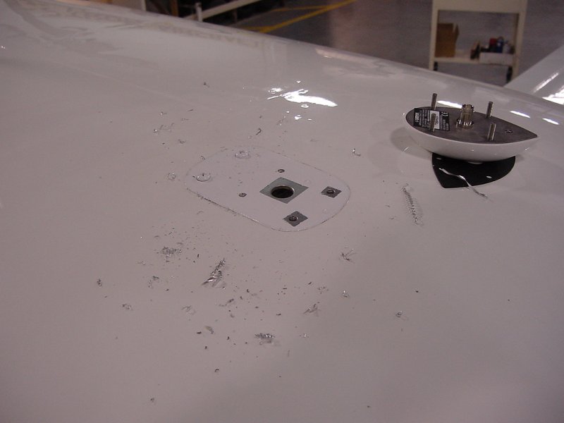
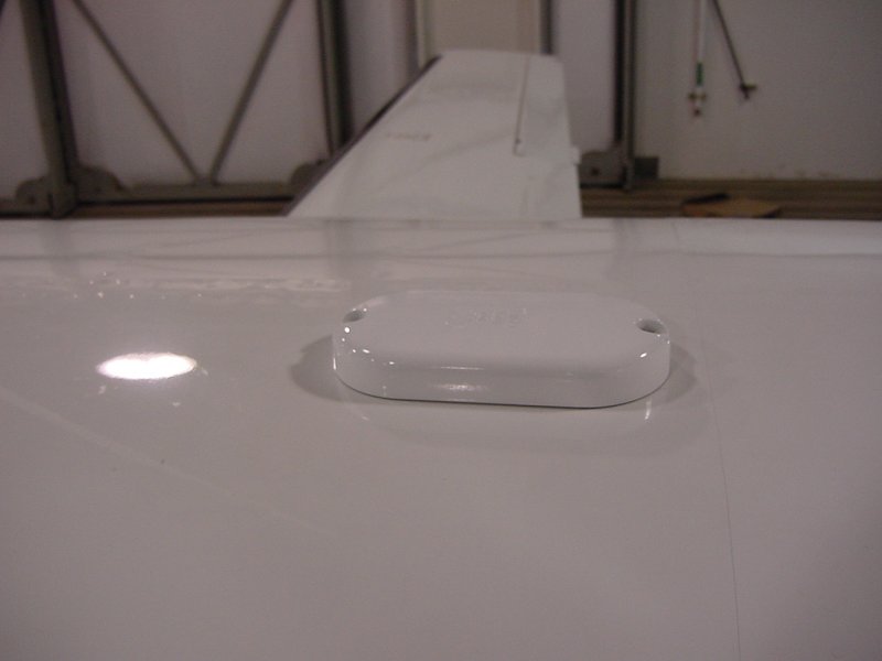
The aluminum showing around a couple of holes on the outside is so that the backing plate makes good electrical contact with the fuselage. On most antennas this is not crucial, but for the WX-500, it is a requirement. With the antenna in place, though not mounted yet (that requires PRC), you can get a sense for what it looks like. Without any sort of scale, it's hard to tell how large this antenna is, but it's only about 8 or 9 inches long.
So right about now, you're probably wondering (as do most people) why this is taking so long: "An entire day just to drill 7 holes and remove a couple pieces of equipment?!" Well, there is a lot of preparation that goes in to every action. When drilling holes in things like planes, especially pressurized ones, you want to make sure you get it right the first time. Because of the care taken when placing these holes, I didn't have to elongate any of them, or make them bigger to accomodate for slop. When removing interior pieces, you have to make sure you don't stress any wires or bend, stretch, or crack anything. When clipping zipties, you have to be sure and not nick any wires (clipping one might be ok, but clipping two at a time leaves you with an hour long job or more of tracing each one to see which one has to be spliced back where). Things are measured, remeasured, tested, and measured again before proceeding with anything permanent.
Maybe tomorrow we'll start wiring up the new equipment, but only after the PRC goes on and the antennas are mounted.
Day 1
Day 2
Day 3
Day 4
Day 5
Day 6
Day 7
Day 8
Day 9
Day 10
Day 11
Day 12