Day 1
Day 2
Day 3
Day 4
Day 5
Day 6
Day 7
Day 8
Day 9
Day 10
Day 11
Day 12
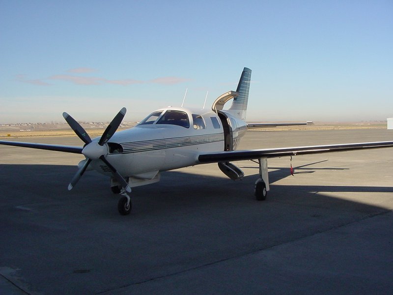
So I recently took a job in the Tri-Cities area installing avionics in general aviation (small) planes. In an effort to illustrate what is involved in a typical installation, I took some pictures during the course of a recent installation in a Piper Mirage (click on the images to get a larger version).
This job will involve removing a couple of older pieces of equipment and replacing them with more recent technology. Since this plane is only 7 years old, and relatively untouched by after-market personnel, it's much easier to work on than some of the older planes. For example, a recent install invovled working on a plane that was over 25 years old and had been maintained by not only a host of mechanics and avionics shops, but also occasionally by the owner. Owner maintenance sometimes results in sub-standard solutions being employed for fairly standard issues. Also, with older planes, the interior and upholstery technology was not as refined, so they are more difficult to work with - not to mention the fact that 25 year old plastic is quite brittle.
The equipment coming out is a King KLN-90B GPS and a King KX-165 Nav/Comm radio. These are being replaced with a Garmin 530. Within a couple months, the transponder will also be replaced with a newer Mode-S variety (Garmin 330) that provides nearby traffic information.
Another piece of avionics going into the plane is a BFGoodrich WX-500 lightning detection system that will display strikes on the 530. The location of the WX-500's antenna is very critical to the correct operation of the system. Since it works on the principal that lightning is an electrical discharge, any electrical noise near the antenna will be picked up and displayed as lightning. To avoid this problem, a "skin mapper" is used which allows us to test a particular location for the antenna prior to cutting holes in the skin of the aircraft.
Since we had limited knowledge of the layout of the Mirage, the first thing that had to happen was some inspection of various compartments on the plane to determine what sort of equpiment was mounted where.
First, we looked in the tail....
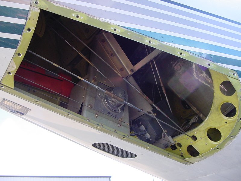
...which housed the servo motors for the rudder and elevator controls for the auto pilot. These are electrical motors which produce a lot of electrical noise. The specs say that the WX-500 antenna has to be mounted at least 4 feet from motors, so the tail is out.
After some consideration, we decided to test out the belly. This plane already had DME, marker, and ADF antennas on the belly, as well as a couple drain holes, so we had limited options and decided this was the best place:
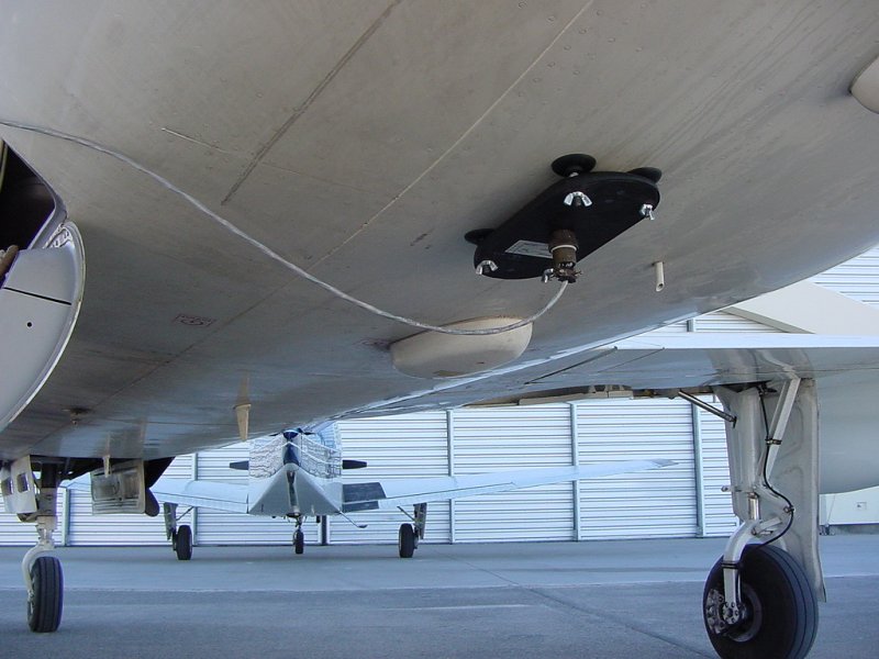
As you can see, the test antenna is attached to the skin using suction cups. The cable runs to a test unit which beeps as "lightning" is detected. More than 2 beeps per second is too much.
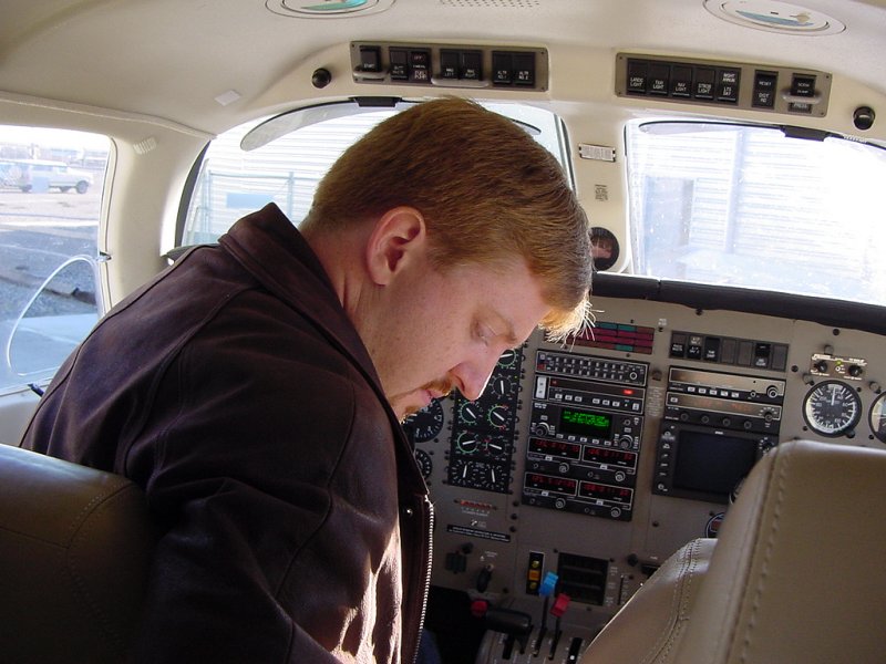
With the antenna in place, we had to do a test run of the engine and all electrical systems to see if anything caused interference with this location. As the pilot of the group, I get the job of doing all engine runs and plane positioning (cool), so here are pictures of me reading up on the starting procedure for a Mirage and during the run-test.
At this point, I turned everything on and off a couple times with the engine up to speed (so that it was supporting the electrical load and not the battery). When it got to deploying the spoilers on the wings, the test box went crazy. Other than that, it was a good spot for the antenna - but this meant we needed to find out 1) why and 2) where else we could mount it.
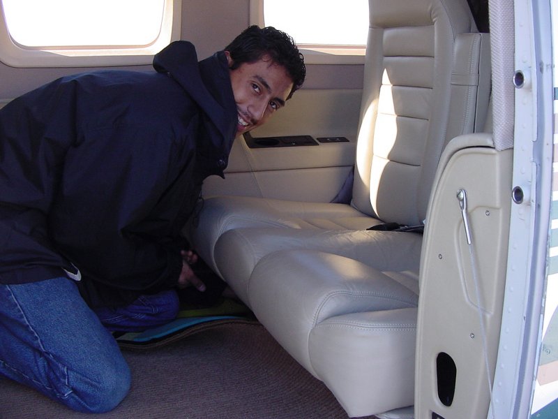
Directly over the belly location was the rear row of seats. Duane, my coworker, is seen here starting the removal of the seats to see what's underneath. Once we got it opened, we found the hydraulic pump to raise the spoilers mounted directly over where we had planned on putting the antenna.
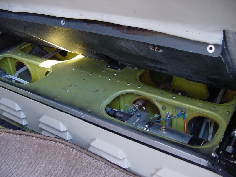
Well then... where else could we put it. Near the front was out because it was too near the engine and battery systems. Anywhere else on the belly was out because of the placement of the existing antennas. So we looked at the top of the plane. With only a couple com antennas, which the WX-500 only needs one foot clearance from, this turned out to be an ideal spot. We did another engine run and determined that it only got one beep when the #1 Comm radio transmissions ended (PTT release). Next was the act of determining how to mount the antenna and if this location was physically feasible.
Since the Mirage is a pressurized airplane, the passenger compartment is tightly sealed from the outside and placed under great pressure at altitude (about 5.5psi, which adds up quick when multiplied by the surface area of the pressure vessel). To provide the structural rigidity necessary to pass FAA certification standards, this means the plane's designers had to place internal ribs every 6 inches or so. The WX-500 antenna is just about 10" long, so it would have to span two sections of skin.
Really the only way to get a good view of where the antenna was going to be mounted was to remove the interior and get a look. Here's some pictures of the interior before we started removing it:
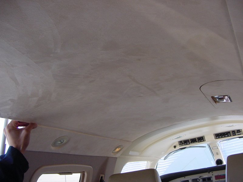
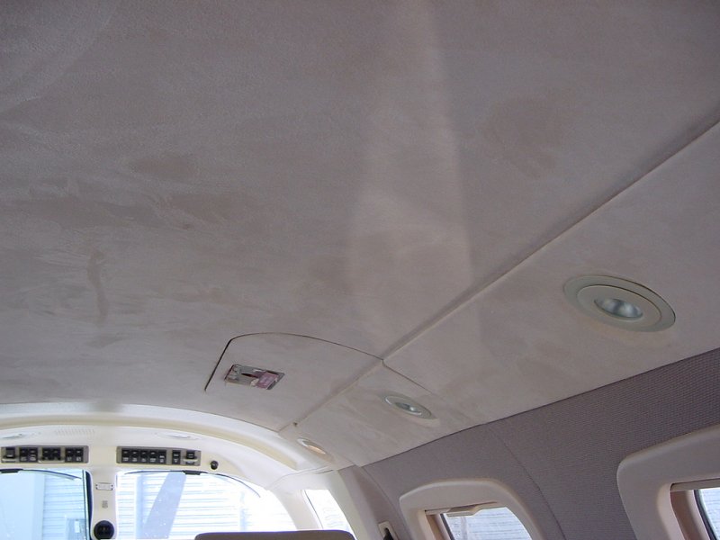
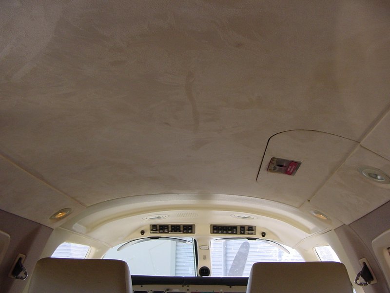
The Mirage is fitted with what Duane calls "Citation" interior - which is business jet class stuff. The headliner is lined with suade and all the fasteners are hidden. For a small single-engine plane, this is really nice stuff. This also means that the people designing the interior have the liberty to make it very difficult to remove. However, the folks at Piper did an excellent job and not only is the interior beautiful, but it's surprisingly easy to remove (getting the single 12 foot piece of fiberglass that makes up the headliner out the single amidships door is another matter). It was a shame we had to dismantle it, but here's what the Mirage looks like when you disrobe its insides:
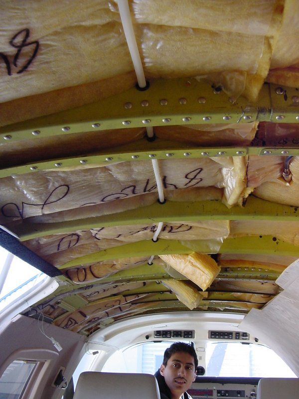
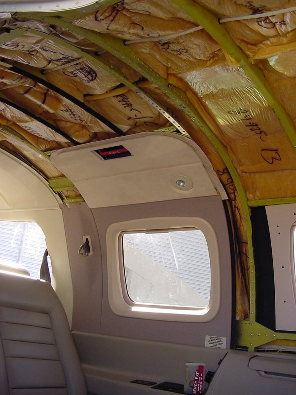
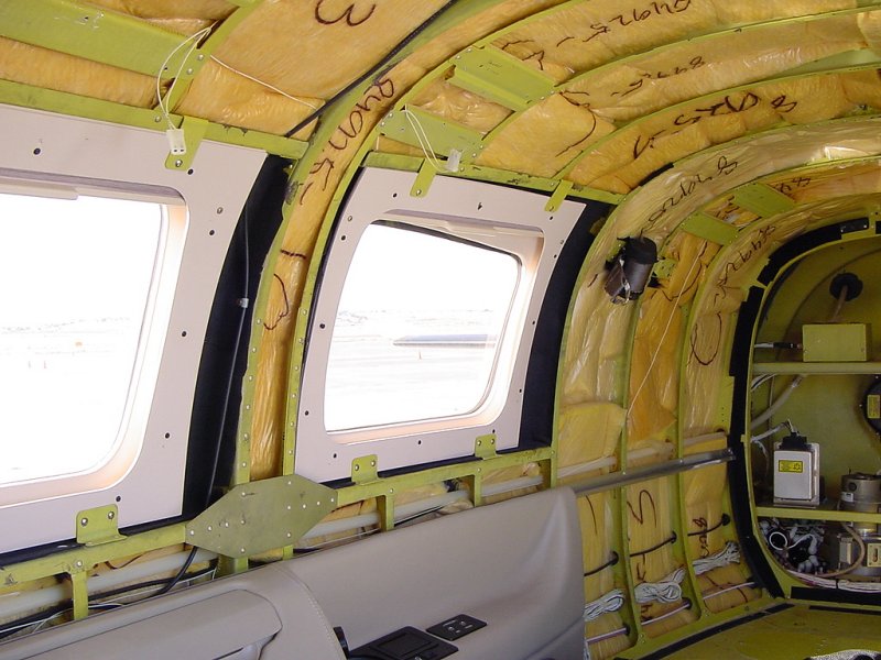
The two sections at the front of the door (with the insulation hanging down) are where we decided to mount the antenna. Not only is the interior nicely designed, but routing wires around behind it is also fairly easy in this plane.
Once we decided the best place to mount the antenna, we had to figure out where to put the processor. The WX-500 system is comprised of three pieces: the antenna, the processor, and the display. Since the WX-500 will display its data on the 530, we won't have to worry about that component, but it still needs a processor mounted somewhere that will take input from the antenna and output the data to the 530. In larger planes, this would be mounted in the equipment bay, but on smaller planes, you stick them where there's room. We found a wonderful place in the Mirage where some of the other equpiment is located that proved to be ideal. There are a couple of shelves for equipment immediately in front of the rear pressure bulkhead that are easy to get to after installation (always a consideration) and are easy to route wires to.
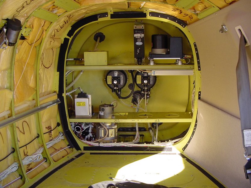
In this picture, you can see (left to right, top to bottom) some Piper box (unlabled), a stall computer, the King KG-102 directional gyro, the yaw damper system, the outflow valves (where the air that's pumped into the cabin escapes), the blank spot where the WX-500 processor will go, and on the bottom, a hydraulic pump for the gear system.
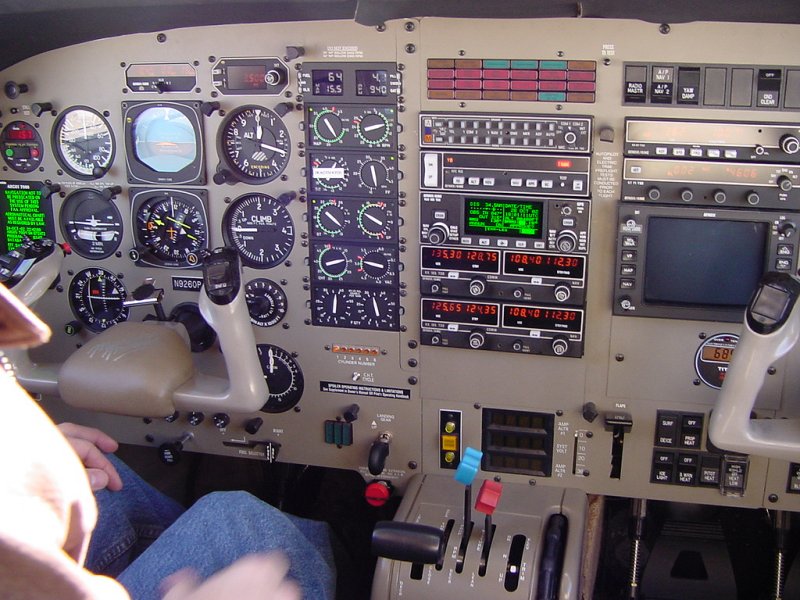
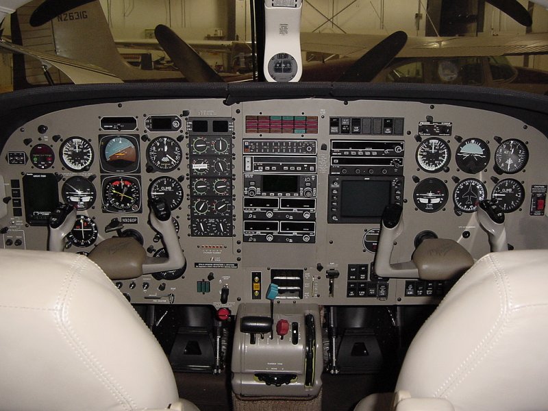
The only other work for the day on this job was to pull the plane in the hanger and start removing the avionics. It's much easier to work on the space behind the panel when you can actually stick your arms in through some holes, so even though only two pieces of equipment are coming out, we remove just about everything we can to gain access to the wire bundles and mounting points. In this picture, you can see what the panel looked like right before I started tearing into it...
...and in this picture, you can see it with the avionics removed from their trays:
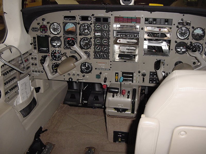
You'll also notice that the pilot's seat has been removed. This is usually one of the first pieces of interior to go since it allows one to get underneath the panel with relative ease. A significant portion of the job is accessing things in the panel from below, so without removing a seat or two, you end up contorting yourself pretty senselessly.
Coming up in day 2, more destruction....
Day 1
Day 2
Day 3
Day 4
Day 5
Day 6
Day 7
Day 8
Day 9
Day 10
Day 11
Day 12