Day 1
Day 2
Day 3
Day 4
Day 5
Day 6
Day 7
Day 8
Day 9
Day 10
Day 11
Day 12
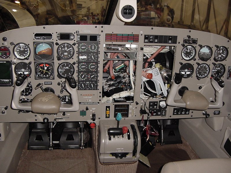
Day two of the installation was focused mainly on getting the rest of the things out that would be in our way during the install. Getting the radios out also protects them from tools and equipment wrangling that might scratch them up.
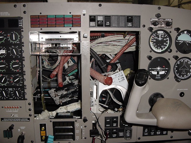
Each radio slides into a tray, which is mounted at the front with four screws, and occasionally supported in the rear with a brace. The back of the tray holds a removable back plate (or back plane depending on your nomenclature) where all the stuff plugs in like cooling air, antenna coax, and other wire connections.
Generally, the trays are long enough that between the back of them and the firewall is only enough room for the bundles of wire that make all the interconnections between equipment. On simpler planes, these bundles might only be 30 or 40 wires thick, or about the thickness of a broomstick (mostly 24 gauge wire). However, on a plane with as much in it as a Mirage, these bundles are sometimes as thick as my arm and can be quite difficult to work around when spacing is tight and they're wrapped up with zipties.
Also, as I mentioned yesterday, the equipment trays hinder access to the wires. So out they come. Here you can see some pictures of the panel with most of the trays pulled out and some of the wire bundles unsecured. The orange hoses are the cooling air (the larger one is actually for window defog), the green connector went to the GPS, and the two backplates below it went to the existing Nav/Coms.
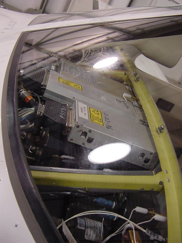
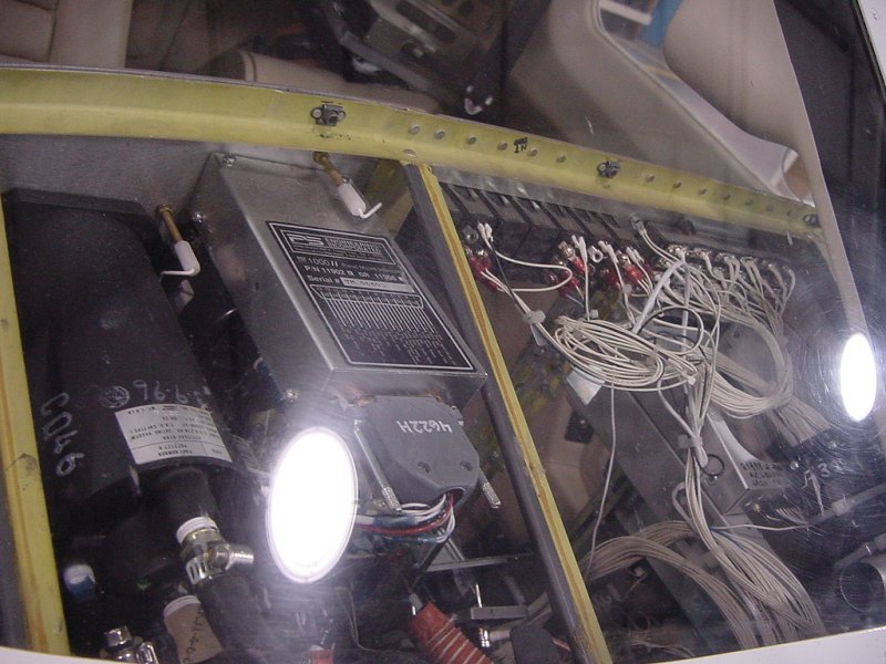
You'll also notice that the glareshield is gone from the top of the panel. On some planes, the glareshield comes out fairly easily (only 3 screws a side on the Mirage) and will give you easy access from the top of things.
To see things from the top, here's some pictures through the front windshield:
In this job, I'll be using mostly wires that went to the radios coming out to hook into the Garmin 530 which combines a moving map GPS receiver and a Nav/Com. To do this, I'll clip one wire at a time off the back of the old connectors, strip it, crimp on a new pin, and snap it into the new connector. Since all the wires are white, and unlabled, a stray wire requires tracing it back through the bundle to determine where it goes. (Another nice thing about new planes is that the wires don't spontaneously snap off the backs of the connectors... like this one plane....)
If more than one wire at a time has to come off because of space restrictions (strippers and crimpers take some working space), the wires get labled as they come off the old connector, and then the labels are removed once they're in the new connector.
So, there you have it - Day 2. Not quite as fun filled as the first day - a lot of the time was spent on the bench determining how to hook all the old stuff into the new gear. Day 3 is just around the corner... we'll see what it holds.
Day 1
Day 2
Day 3
Day 4
Day 5
Day 6
Day 7
Day 8
Day 9
Day 10
Day 11
Day 12